|
Drill bits,Saw blades,Lawn mowers,Angle grinders|Garden Tools,Power Tools,Cutting Tools Supplier!
|
 |
Main Technical Conditions Of Twist
Drill
1). DimensionsDrill diameterThe values
indicated in the relevant dimensional standards
apply in respect of the diameter of Twist
Drills.
Test point: On the lands at the
corners,(see Fig.l)
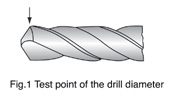
Testing equipment: micrometer
Tapering of diameter:The
diameter of twist drills usually reduces from
the drill tip towards the shank in the area of
the flutes.
Test values:The taper on
diameter amounts to 0.02 to 0.08mm over a length
of 100mm.
Test point: At the outside diameter
on the land.
Testing equipment: micrometer
and indicating measuring instruments.
Parallel shank :Tolerance
for shank diameter f11,Tolerance for roundness
and parallelism 0.02mm for the shank length.
Concentricity tolorance(Tr.) The concentricity tolerance(Tr.) of
the Twist Drill is calculated from the equation.
Tr=O.03+O.O11/d
In
which I is the total length and d the diameter
of the drill (all dimensions in mm)
Length:The tolerance of
length for the total length corresponds for the
degree of accuracy very coarse according to DIN
7168 part 1.The flute lengths given in the
relevant dimensional stands are minimum
dimensions.
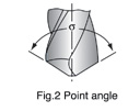
Point angle:Test
value:σ=118°;σ135°
Test point: At the cutting
edges(See Fig.2)
Testing equipment: Universal
bevel protractor indicating measuring
instruments.
2). Materials and
hardnessMaterials: M2; M35i M42;
F4341; 93410r4341;
Hardness:HSS HRC63-66
HSSCO HRC64-68
Test point: On outside
diameter on the land or adjacent relieved
land.
Test equipment: Hardness Tester.
3).
Making:Twist drills with
diameter 3mm and upwards shall be marked
with:
Diameter
Material:(HSS;HSSCO;)
Name or mark of
manufacturer.
Additional and/or differing
marking by agreement.
4). Twist Drill
with parallel shank 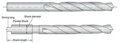
5). Twist Drill
with taper shank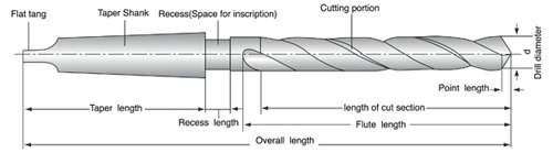
6). General
dimensions of morse taper
shanks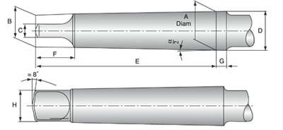
| Morse Taper Shank
A mmB mmC(h13)
mmD mmE mmF(max.) mm
G mmH(max.)
mm |
α/2 |
| No.1 12.06595.2
12.26213.53.58.7 |
1°25’43 |
| NO.217.780146.3 18.07516513.5 |
1°25’50 |
| NO.323.82519.17.924.19420518.5 |
1°26’16 |
| NO.431.26725.211,931.6117.5246.524.5 |
1°29’15 |
| NO.544.39936.515.9 44.7149.5296.535.7 |
1°30’26 |
| NO.663.34852.41963.821040851 |
1°29’36 |
7). Cutting portion 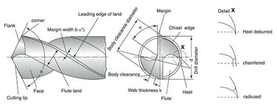 σ= Point angle (sigma) σ= Point angle (sigma)
ψ = Chisel edge
angle(psi)
*)In the context of cutting
technology, land width b is the body clearance
land width which is to be by bfan see
DIN 6581.
8).
Angle at the cutting edges The corner has been adopted as the
observed edge point
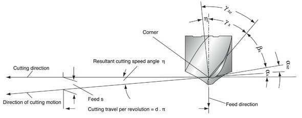
αx=Side clearance angle
(alpha)
αxe=Effective side
clearance angle
βx=Side wedge
angle(beta)
γx=Front rake
angle(gamma)
γxe=Working front
rake angle
η=Resultant cutting speed
angle(eta)Clearance angle α,wedge angle β and rake
angleγare measured in the tool orthogonal plane.
For details, see DIN 6581, definitions of
metal-cutting technology; geometry at the tool
edge.
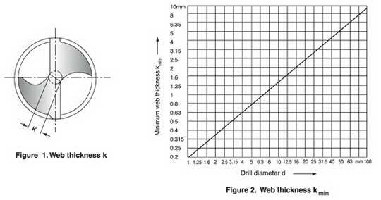
9). Web thickness
KTest values:The web
thickness according to Fig.1 shall not be less
than the minimum value kmin indicated
in Fig.2.Test point: At
the point of the drill.
Testing
equipment:Slide gauge with measuring
points.
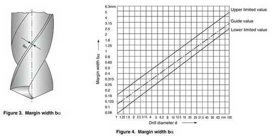
10). Margin width
bα Test values: The land width
as in Fig.3 shall lie within the limitting
values indicated in Fig.4 Test
point: 5mm behind the corner
Testing equipment: Slide
gauge
11). Angle on
twist drills (1)Side rake angle γf (Helix angle) Recommended
test value: Recommended ranges
depending on the tool types N,H and W according
to DIN 1836 and the diameter of the drill
included in Fig.5
Test point: At the corner, see Fig.6
Testing equipment: According to VDI Guideline 3331 Part1
,Section Margin widthbα
Note:The side rake angle
γfis measured in place of the
orthonagonal rake angle γo found in
the wedge measuring plane(see DIN 6581),as this
changes along the cutting edge(becoming smaller
towards the point of the drill)
(2) Point angle σ
test value: Usual
executin for tool types N and H:σ =118°,for tool
type W:σ =130°
Test point: At the cutting, see Fig.7.
Testing
equipment: According to VDI Guideline
3331 Part 1, Section Margin width
bα
12). Resharpening
Twist drills (1) Drills are worn off
irregularly.It should be sharpened prior to
developing into excessive wear.(2)
Resharpening
①Grind the correct
point angle to suit your application.(figure 8)
②Check that both cutting lips have the same
angle. On a 130° point,each lip should be 65°
toward the axis.The point must be on center,
i.e.,the chisel edge must produce cutting lips
of equal length.(figure 8)
③Grind Primary
relief and Secondary clearance,(figure
9)
④Grind web thinning.(figure 10)
13). Web
Thinning (1) Without thinning
Suitable for drill of
general purpose.Thanks to thin web thickness,
web thinning is not need.
This without web
thinning type is applied to design of drills for
mild steel, alloy steels, cast iron, stainless
steel, titanium, inconel, etc. and conventional
cutting conditons.
(2) Type C thinning
(DIN 1412 FORM C,SPLIT POINT)
Because Split
point enables good centering
when drilling
and breaks the chips,chip removals is
easy.
Suitable for drill design in high
hardened tough materials,i.e, heat treated
steel, titanium alloy,
stainless steel, incoroy inconel, nimonic,
etc.
(3) Type R thinning (HEI.ICAL
THINNING)
Helical thinning ensure to frequent
chip breaking and removal. The different
direction force of cutting edges and helical
thinning parts enables that chips curl, break
and remove through the flutes. In addition
helical thinning makes the chip room up to
center, remove the chisel and enables good
centering.(4)Type A thinning (DIN1412 FORM A)
A type
thinnings makes thin chisel, good chip removal
and favorable centering.
This type is the
easiest type to grind the thinning. In narrow
web and wide fluted drills,keeping of the
rigidity and smooth chip removal are
possible.(5) Type B thinning (DIN1412 FORM B)
In
case of work materials with low cutting
resistance and good chip removal,ie,cast
iron,aluminium, plastic etc, B type thinning is
suitable.
Especially when drills for high
hardended steels are designed, this type is
applied to decrease rake angle and avoid
chipping of cutting
lips. |
